Why Is DC Isolation Different From AC Isolation? The answer begins with a simple question: What is the difference between DC and AC isolation? The challenge is not only separating two circuits. Engineers must control voltage, current, frequency, energy storage, and unintended coupling across the barrier.
DC isolation usually means preventing steady current from crossing between circuit domains. A transformer cannot pass steady-state DC. Therefore, designers often convert DC into a switching waveform, transfer energy magnetically, and rectify it again. Optocouplers, digital isolators, and isolated converters can also transfer signals or power. Small parasitic capacitances still matter. A fast voltage edge can drive displacement current through them.
AC isolation behaves differently because alternating voltage naturally interacts with capacitance and inductance. A transformer can transfer AC energy without a direct conductive path. However, higher frequency may increase leakage current, electromagnetic interference, and insulation stress. The physical gap remains. The electrical behavior does not.
Dr. Robert W. Erickson, a respected power-electronics researcher, offers a useful principle: “Isolation is a system property, not merely a component feature.” That statement deserves careful attention. A certified isolator cannot compensate for poor PCB spacing, weak insulation, or incorrect grounding. Creepage and clearance need inspection. Transient conditions need testing. Real installations are rarely perfect.
This article examines both isolation methods through practical design details. It also questions a common assumption: a visible barrier does not always guarantee safe isolation. Sometimes, the smallest hidden capacitance becomes the decisive path.
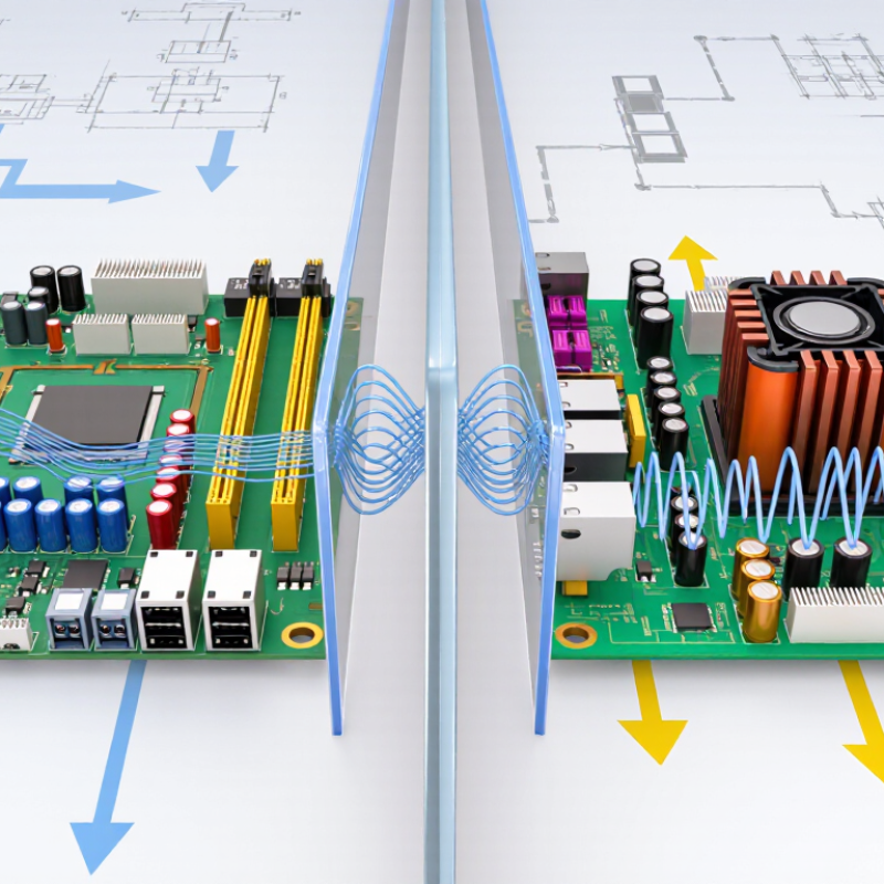
Electrical isolation means preventing unwanted current from flowing directly between two circuits while allowing energy or information to pass safely. In DC systems, isolation cannot rely on a steady magnetic field through an ordinary transformer. A DC-to-DC converter must first switch the input into a changing waveform, transfer energy across an isolated transformer, then rectify it again. The output may be electrically separate, but its voltage can still rise quickly during switching faults. A small gap does not guarantee safety.
AC isolation often uses a transformer, where alternating current creates a changing magnetic field. The primary and secondary windings share energy without a conductive connection. Even so, the isolation barrier must withstand working voltage, surges, and repeated temperature changes. Designers also consider creepage, clearance, insulation layers, and stray capacitance. High-frequency AC can cross a barrier through tiny capacitive paths, creating leakage current that a basic continuity test will not reveal.
In practical testing, an engineer may measure resistance first, then apply an insulation test at the specified voltage. The result needs careful interpretation. A meter can show “open,” yet fast switching edges may still couple noise into the isolated side. This is where DC and AC isolation become different in behavior, not merely in terminology. I have found that diagrams make the boundary look cleaner than real hardware. Layout, cable position, humidity, and measurement technique can change the result. Safety decisions should follow verified specifications and competent electrical review.
An isolation barrier separates circuits without a direct conductive path. With ideal DC isolation, steady current cannot cross that barrier. However, real barriers contain small parasitic capacitances. A sudden voltage change can therefore create a brief displacement current. The edge matters.
AC behaves differently because its voltage changes continuously. A transformer can transfer alternating energy through magnetic coupling while blocking the original DC component. Capacitive coupling can also pass AC, especially at higher frequencies. Its performance depends on frequency, capacitance, insulation distance, and the barrier’s construction.
In bench testing, a multimeter may show no DC continuity across an isolated supply. That result does not prove complete electrical silence. An oscilloscope can reveal narrow current spikes when switching begins. These spikes may disturb sensitive measurements or communication lines.
A common mistake is treating isolation as an absolute wall. It is more accurate to view it as a controlled impedance across frequency.
Engineers check insulation resistance, withstand voltage, leakage current, creepage, clearance, and common-mode noise. They also test fast transients, not only steady voltage. A design that passes a slow test may still behave poorly during rapid switching.
This is where practical judgment matters. Theory alone can miss the awkward details.
Why Is DC Isolation Different From AC Isolation?
Transformer isolation works naturally with AC because AC keeps changing direction. That changing current creates a changing magnetic field in the transformer core. The field then induces a voltage in the separate secondary winding, without a direct conductive connection.
A typical bench test makes this visible. Apply a low-frequency AC signal to the primary, and the secondary produces a related waveform. Touching the two circuits together is unnecessary. The insulation and spacing provide the physical barrier. Small stray capacitances still exist, however. Isolation is never perfectly magical.
Apply steady DC to the primary, and the transformer behaves differently. A brief switching transient may appear at the secondary. Then the core approaches saturation, while the primary current rises sharply. No changing magnetic field means no sustained transferred voltage. That is the important distinction.
DC systems need another method. A converter can switch DC rapidly, creating an AC-like waveform for the transformer. Optical, magnetic, or capacitive isolators can also transfer information across a barrier. Each method has limits involving timing, leakage, noise, and fault conditions. Engineers must check creepage, clearance, insulation ratings, and transient behavior.
The detail I often reconsider is frequency. Higher frequency can reduce transformer size, but it may increase switching losses and electromagnetic noise. Lower frequency may improve simplicity, yet it often requires more core material. Good isolation is therefore not just a component choice. It is a measured design decision.
A transformer transfers changing magnetic flux, so it naturally passes AC but not steady-state DC.
The chart compares a 1:1 ideal transformer supplied by 120 V RMS, 60 Hz AC with the same transformer supplied by 120 V DC. For AC, the secondary reproduces the changing waveform and provides galvanic isolation. With steady DC, the magnetic flux does not continuously change, so the transformer produces no sustained secondary voltage; practical DC application would also drive the core toward saturation.
AC isolation is often straightforward because transformers transfer energy through a changing magnetic field. A steady DC signal cannot create that continuing change. Once the magnetic core reaches a fixed state, energy transfer stops. That is the central difference. DC therefore needs switching, capacitive coupling, optical transfer, or another galvanic isolation method.
In practice, an isolated DC converter rapidly switches the input voltage. A transformer then transfers high-frequency energy across the barrier. Rectification and feedback rebuild a stable output. Digital isolators and optocouplers can transfer control signals without direct electrical contact.
The design must also manage leakage current, insulation distance, electromagnetic noise, and fault energy. Small gaps matter.
The need is expanding. The International Energy Agency reported nearly 510 GW of renewable capacity additions in 2023. Solar power represented about three-quarters of that growth, creating more DC-heavy systems. Its Global EV Outlook 2024 recorded more than 14 million electric car sales in 2023, approximately 35% higher than the previous year. Batteries and photovoltaic arrays both deliver DC power.
Field commissioning shows a common mistake: treating DC like low-frequency AC. That shortcut can produce unstable feedback or dangerous stored energy. Engineers should verify isolation under real load, temperature, switching frequency, and fault conditions. Laboratory readings alone may not reveal every weakness.
DC isolation differs from AC isolation because current behaves differently after switching. With AC, the waveform crosses zero repeatedly. That natural zero can help extinguish an opening arc. DC has no routine zero crossing. An arc may continue, stretch, and damage contacts. In practical inspections, I treat every DC disconnect as an energy-control device, not a simple switch. Small systems still deserve respect.
Safety design must account for polarity, stored energy, and possible reverse current. A DC isolator needs suitable voltage and current ratings for the actual circuit. It must interrupt the circuit safely under the expected load. AC-rated equipment may fail in DC service, even when the numbers look similar. Clear spacing, arc barriers, and secure terminals reduce flashover risks. Capacitors can remain charged after isolation. Verification matters. Use an approved meter, test the circuit, and test the meter again.
Reliable procedures also identify multiple energy paths, including batteries, converters, and backfeed sources. Labels should show polarity and isolation points clearly. A visible gap can provide confidence, but it does not prove zero voltage. That distinction is easy to forget during rushed maintenance. I have seen drawings omit a return path; field conditions were less tidy. That mistake deserves review.
| Design and Safety Dimension | DC Isolation | AC Isolation | Key Engineering Implication |
|---|---|---|---|
| Current zero crossing | A steady DC current does not naturally pass through zero during normal operation. | Alternating current normally crosses zero twice per cycle; at 50 Hz this occurs about every 10 ms, and at 60 Hz about every 8.33 ms. | AC interruption can benefit from natural current zeros, while DC switching must actively force or control arc extinction. |
| Arc behavior during disconnection | An arc can continue across opening contacts if the electric field and available energy are sufficient. | The arc is more likely to extinguish near a natural current zero, subject to voltage, current, power factor, and device design. | A DC isolator requires suitable contact spacing, magnetic arc blowout, arc chambers, or another approved interruption method. |
| Polarity and switching paths | Positive and negative conductors may both remain energized relative to ground, depending on the system arrangement. | Line and neutral conductors have different functions, and the required isolation points depend on the earthing and supply system. | The isolator must switch every conductor required by the applicable electrical code and system design; polarity markings are especially important for DC. |
| Stored electrical energy | Batteries, photovoltaic modules, and DC-link capacitors can continue supplying voltage or current after a switch is opened. | Transformers and capacitors can also retain or transfer energy, but the source characteristics and discharge paths are different. | Isolation procedures must identify all independent sources and allow sufficient time or circuitry for stored energy to discharge. |
| Voltage polarity after isolation | The polarity remains fixed, and capacitive or inductive circuits may produce unexpected voltage if terminals are left floating. | The voltage alternates in polarity, and open conductors may show induced or back-fed voltage from other circuits. | Verification must test for absence of voltage using equipment rated for the circuit and suitable for the expected voltage type. |
| Isolation device rating | The device must be specifically rated for the DC voltage, continuous current, short-circuit conditions, and number of poles. | The device must be rated for the AC voltage, current, frequency, utilization category, and prospective fault current. | An AC-only switch should not be assumed suitable for DC; ratings are not automatically interchangeable. |
| Fault current characteristics | Batteries and power converters can deliver substantial fault current, while PV fault current is often limited by irradiance and converter behavior. | Utility supplies can provide high prospective short-circuit current, with current magnitude influenced by source impedance and network conditions. | Protection and isolation equipment must be selected from the actual source fault study, not from voltage alone. |
| Inductive load interruption | Inductors resist rapid current change and can generate high transient voltage when the current path is opened. | The alternating waveform and current zero can assist interruption, but inductive loads may still create significant switching transients. | DC designs commonly require suppression such as a flyback diode, snubber, varistor, or a properly engineered semiconductor switch. |
| Discharge and verification | Open-circuit voltage may remain present until capacitors discharge or the source is physically disconnected. | Voltage may be absent at one point but reappear through backfeed, stored energy, or an alternate supply path. | Use a documented lockout or isolation procedure: identify sources, isolate, lock and label, test, discharge where required, and re-test. |
| Typical applications | Battery systems, solar photovoltaic arrays, electric vehicles, data-center DC systems, control circuits, and converter DC links. | Utility distribution, motors, transformers, building wiring, industrial machinery, and general-purpose power systems. | The isolation method should be selected for the complete system, including source type, load type, fault level, grounding method, and applicable standards. |
Safety note: Always use isolation equipment, testing procedures, and protective measures that are appropriate for the actual voltage, current, fault level, and applicable electrical standards.
Electrical isolation prevents direct current flow between circuits. Energy or information may still cross safely. The circuits remain electrically separate.
A transformer needs a changing magnetic field. Steady DC quickly reaches a fixed magnetic state. Energy transfer then stops.
It switches the input into a changing waveform. An isolated transformer transfers the energy. Rectifiers rebuild the output voltage.
AC isolation often uses separate transformer windings. Alternating current creates a changing magnetic field. Energy crosses without a conductive connection.
No. A small gap cannot prove safe isolation. Voltage can rise during switching faults. Stored capacitors may remain charged.
AC naturally crosses zero during each cycle. DC has no routine zero crossing. An arc may continue and damage contacts.
Check voltage, current, polarity, stored energy, and reverse current. The device must interrupt the actual circuit safely. Similar numbers can mislead.
Measure resistance first, then apply the specified insulation test voltage. Use an approved meter. Test the circuit, then test the meter again.
Yes. High-frequency switching can cross through stray capacitance. A meter may show “open,” while fast edges still couple noise.
Cable position, layout, humidity, temperature changes, and measurement technique all matter. Drawings can look cleaner than hardware. Review field conditions honestly.
Electrical isolation is the practice of separating circuits so that power or signals can be transferred without creating a direct conductive path. What is the difference between DC and AC isolation? The main difference is how each type of current interacts with the isolation barrier. AC voltage changes direction continuously, allowing energy to pass through magnetic or capacitive coupling. DC voltage remains at a constant polarity, so it cannot pass through a transformer in its steady state without additional circuit techniques.
Transformer isolation therefore works naturally with AC because alternating current produces a changing magnetic field in the transformer core. For DC systems, isolation usually requires switching the DC into a high-frequency AC waveform before transferring and then rectifying it back to DC, or using another suitable isolated conversion method. These differences affect safety, insulation requirements, leakage current, grounding, fault protection, efficiency, and system design. Careful consideration of voltage, current, switching behavior, and fault conditions is essential when selecting an isolation approach.

SDEV Charger