How to Choose Residual Current Devices for Solar PV?

Time:2026-09-16 Author:Madeline
0%

Choosing a residual current device for a solar PV system requires more than matching a current rating. The device must suit the inverter, earthing arrangement, leakage characteristics, and installation environment. What are residual current devices in solar PV? They monitor current balance between live conductors and disconnect the circuit when leakage reaches a dangerous level. In simple terms, they act like a fast safety gate. They can reduce electric shock risks and limit damage caused by insulation faults.

Solar installations create special challenges. Inverters may produce smooth DC residual currents, high-frequency leakage, or short transients during startup. A Type AC device may therefore be unsuitable for some modern inverter designs. Type A or Type B protection might be required, depending on the manufacturer’s instructions and the inverter’s internal safeguards. The answer is never based on the panel wattage alone. Check the inverter manual, system diagram, rated current, trip sensitivity, pole configuration, and expected leakage before selecting a device.

Small details matter. A rooftop array may face rain, heat, dust, and repeated thermal cycling. An RCD installed in a crowded enclosure may also experience unwanted tripping. That problem is frustrating, but ignoring it is worse. Experienced electricians verify compatibility, test the completed circuit, and record the results. Still, no guide can replace site-specific design judgment. Local electrical requirements and qualified inspection remain essential. A careful selection balances protection, reliability, maintainability, and realistic operating conditions.
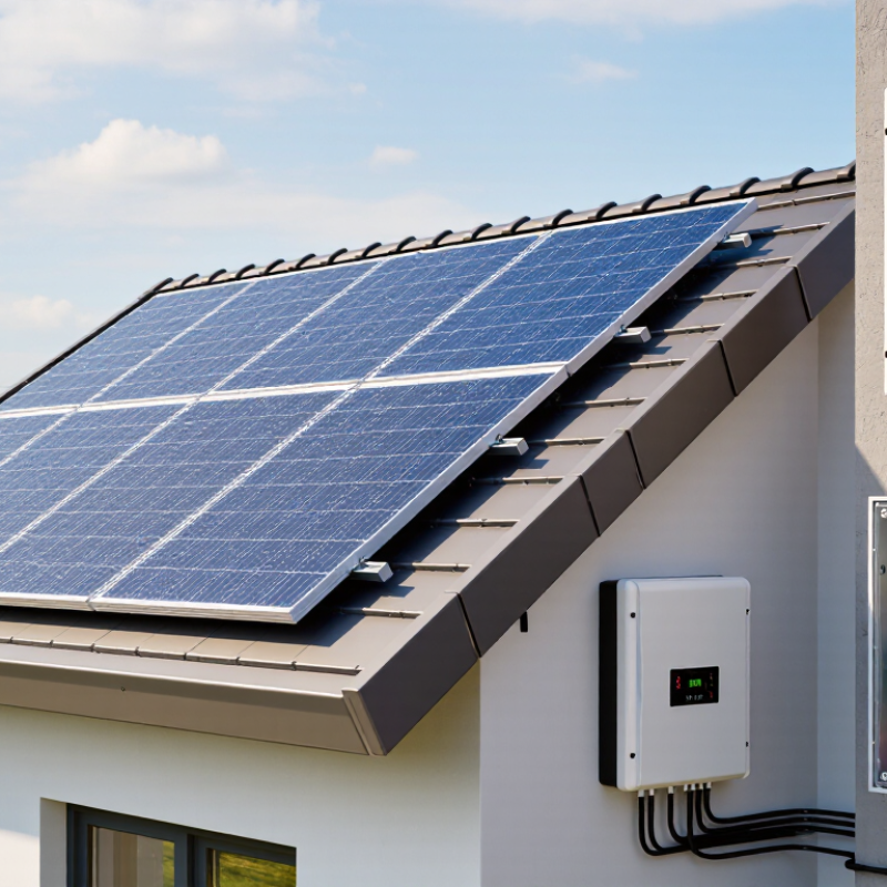
How to Choose Residual Current Devices for Solar PV?

Understanding Residual Current Risks in Solar PV Systems

How to Choose Residual Current Devices for Solar PV?

Understanding Residual Current Risks in Solar PV Systems

A solar PV system can produce residual current in several ways. Damaged insulation, wet connectors, and aging cables are common contributors. Inverter filters also create small leakage currents during normal operation. These currents may increase when panels, junction boxes, or cable routes become damp.

The inverter’s internal design matters greatly. Transformerless inverters can generate smooth DC residual currents during certain faults. A standard device may not detect them correctly, or it may lose sensitivity. Check the inverter documentation before selecting the RCD type. Type A may be suitable in some systems, while Type B or another specified solution may be required. Never choose by price alone.

Rated residual operating current needs careful attention. A 30 mA device is often used for additional personal protection, subject to local requirements and system design. Higher settings may support fire protection or reduce nuisance tripping, but they cannot replace proper insulation testing. The RCD should also match the circuit rating, fault conditions, and expected leakage from multiple inverters.

Test the device during commissioning. Test it again after major maintenance. A trip button check is useful, but it cannot reveal every wiring problem. Measure insulation resistance and investigate repeated tripping instead of simply fitting a higher-rated device. That shortcut can hide a serious fault. In practice, clean drawings are not enough; moisture under a connector can defeat a careful design. Connection details deserve another look.

Common residual operating current ratings used for RCD selection include 10 mA, 30 mA, 100 mA, 300 mA, and 500 mA. A lower rating provides greater sensitivity, while higher ratings are generally used where equipment leakage or installation conditions could cause unwanted tripping. The correct RCD type and rating must be selected according to the PV inverter design, local electrical regulations, earthing system, and manufacturer instructions.

Identifying RCD Types for Different PV Inverter Designs

As solar deployment expands, RCD selection must follow inverter design, not habit. The IEA PVPS Trends in Photovoltaic Applications 2024 report recorded more than 1.6 terawatts of global PV capacity by the end of 2023. This scale increases the need for consistent protection decisions. Transformerless inverters can produce AC, pulsating DC, or smooth DC residual currents. A Type AC RCD may not respond correctly to these mixed waveforms. Type A can suit some single-phase inverters, provided the inverter includes certified monitoring that limits smooth DC leakage. Type B is often required for three-phase or transformerless designs where DC current can remain on the protective conductor.

The correct choice depends on the inverter manual, earthing arrangement, and measured leakage current. IEC 60364-7-712 and IEC 60755 provide important design references, but site conditions still matter. Long DC cable runs, moisture, filters, and several inverters can increase nuisance tripping. I have seen installations pass functional checks, then trip repeatedly after heavy rain. That detail is easy to underestimate.

Tips: Confirm the inverter’s residual-current waveform classification before ordering the RCD. Check whether a Type B device is mandatory or whether approved internal DC monitoring permits Type A. Use a 30 mA device only where the protection design requires additional personal protection. Test the installed RCD under realistic operating conditions, including startup and maximum generation. A neat drawing is not proof of compatibility. Have a qualified electrician verify local requirements and record the test results.

How to Choose Residual Current Devices for Solar PV? – Identifying RCD Types for Different PV Inverter Designs

PV Inverter Design Possible Residual-Current Waveforms Typical RCD Type to Evaluate Technical Reason Important Selection Conditions
Transformer-isolated inverter with no conductive DC connection to the AC side Primarily sinusoidal AC residual current, subject to the actual inverter topology and fault conditions Type AC or Type A, only when expressly permitted by the inverter documentation and local installation rules Galvanic isolation can reduce the likelihood of smooth DC residual current reaching the AC circuit Confirm whether the inverter can generate pulsating DC, high-frequency components, or other non-sinusoidal residual currents. Type AC does not detect smooth DC or pulsating DC.
Transformerless inverter with integrated residual-current monitoring and DC detection AC, pulsating DC, and potentially smooth DC components under fault conditions Usually Type A; Type B may still be required if specified by the manufacturer, design standard, or risk assessment The inverter’s certified monitoring function may detect or disconnect for DC residual current before the upstream RCD becomes desensitized Verify the specified DC detection threshold, disconnection time, compatible RCD types, and any restrictions on the use of Type A devices.
Transformerless inverter without documented DC residual-current monitoring AC, pulsating DC, and smooth DC residual current may occur Type B is generally the most comprehensive option to evaluate Type B RCDs are designed to respond to AC, pulsating DC, and smooth DC residual currents, including certain higher-frequency components Do not assume that Type A is suitable without written inverter information. Confirm the RCD operating range, frequency response, short-circuit rating, and coordination requirements.
Single-phase inverter with frequency-variable or high-frequency switching stages AC, pulsating DC, mixed-frequency AC, and possible DC components Type F or Type B, subject to the inverter manufacturer’s compatibility statement Type F is intended for certain single-phase loads with mixed-frequency residual currents, while Type B provides broader detection capability including smooth DC Type F is not a universal substitute for Type B. Use it only when the expected waveform and manufacturer requirements fall within its specified operating range.
Hybrid PV inverter with battery charging and discharging functions AC, pulsating DC, smooth DC, and switching-frequency components from both PV and battery power stages Type B, or the exact type stated in the inverter installation instructions Bidirectional power conversion can introduce residual-current waveforms that are not reliably detected by Type AC or Type A devices Evaluate each operating mode, including grid-connected, backup, charging, and islanded operation. Check whether separate RCD protection is required for backup outputs.
PV inverter supplying motor drives, heat pumps, or other power-electronic equipment AC, pulsating DC, smooth DC, and variable-frequency residual currents Type B is commonly evaluated; Type F may be suitable for specific single-phase applications Multiple electronic converters can create residual-current waveforms outside the detection capability of Type AC and some Type A devices Assess the complete downstream installation, not only the PV inverter. The final RCD type must match the equipment with the greatest residual-current risk.
Multiple inverters connected to a common AC distribution board Combined AC, pulsating DC, smooth DC, and high-frequency residual currents Type B may be required for the common upstream protective device; individual circuits may use different types Residual currents from several converters can add together and may affect the operation of an upstream RCD Check cumulative leakage current, selectivity, time delay, rated current, and the manufacturer’s permitted maximum number of inverters per RCD.
AC-coupled battery inverter installed alongside a separate PV inverter Waveforms produced by both independent bidirectional and unidirectional converters Type B or the combination specified by the equipment manufacturers The battery converter can introduce smooth DC and mixed-frequency residual currents that influence the upstream protection Confirm whether each converter has independent DC monitoring and whether the upstream RCD is approved for simultaneous operation of both systems.
Selection note: RCD type alone does not determine the complete protection design. Select the rated residual operating current, rated current, number of poles, short-circuit capability, time delay, selectivity, environmental rating, and disconnection time according to the applicable electrical installation standard, local regulations, system earthing arrangement, and the PV inverter manufacturer’s instructions.
RCD type reference: Type AC detects sinusoidal AC residual current; Type A detects sinusoidal AC and pulsating DC residual current; Type F is intended for specified single-phase mixed-frequency applications; Type B detects AC, pulsating DC, smooth DC, and defined higher-frequency residual-current components. Always verify the actual product standard and operating frequency range.

Matching RCD Ratings to System Current and Voltage

Choosing a residual current device (RCD) for a solar PV system requires more than reading the inverter label. Match the RCD’s rated current to the circuit’s maximum continuous current. For example, a 32 A circuit should not use a device rated below 32 A. Leave sensible capacity for temperature, cable grouping, and future operating changes.

Voltage matching is equally important. The RCD’s rated voltage must meet or exceed the AC system voltage, such as 230 V single-phase or 400 V three-phase. Do not confuse this rating with the PV array’s DC voltage. DC strings require equipment designed for their voltage and fault conditions. An AC RCD cannot automatically provide suitable DC protection.

Select the residual operating current, IΔn, according to the design and local electrical requirements. A 30 mA device is commonly used for additional protection, but inverter leakage can cause unwanted trips. Type A or Type B devices may be necessary when the inverter can produce pulsating or smooth residual DC, depending on its internal protection. Check the inverter documentation and applicable standards, such as IEC 60364-7-712. The RCD also needs separate overcurrent protection; it does not replace a circuit breaker. A clamp meter can reveal startup current and leakage during bright midday operation. Small details matter. I have seen ratings chosen from nominal output alone, while real cable temperature and inverter behavior were overlooked. Rechecking those assumptions is worthwhile.

Checking Installation Conditions and Electrical Standards

Choosing a residual current device for a solar PV system starts with the installation environment. Inspect the roof, inverter location, cable routes, and distribution board. Heat, moisture, dust, and ultraviolet exposure can affect device performance. The enclosure should suit the site’s IP rating requirements. Check ambient temperature and altitude limits too. Small details matter.

The electrical arrangement must be identified before selecting the RCD. Confirm whether the system uses a TT, TN-S, or another earthing arrangement. Review the inverter’s leakage current and its protection requirements. Some equipment may require Type A protection, while systems with possible smooth DC residual currents may require Type B protection. IEC 60364-7-712 and relevant national wiring rules provide useful technical guidance, but local regulations always control the final design.

Coordination also deserves attention. The RCD’s rated residual operating current should balance shock protection, fire risk, and unavoidable PV leakage. Excessive sensitivity can cause nuisance tripping, especially during wet weather. Check selectivity between upstream and downstream devices. Test the installation after commissioning, not only the RCD test button. A button test confirms limited operation, not the complete protective system.

A common inspection mistake is choosing the device from current rating alone. That approach looks tidy but misses waveform, earthing, and environmental factors. Installation records should include test results, settings, circuit diagrams, and the applicable standards. A qualified electrician should verify the final selection and reassess it after inverter replacement or system expansion.

Testing, Maintaining, and Replacing RCDs Safely

How to Choose Residual Current Devices for Solar PV?

Solar PV growth makes reliable RCD maintenance more important. The IEA PVPS Trends 2024 report recorded 456 GW of new solar capacity in 2023, pushing global capacity beyond 1.6 TW. Each installation needs an RCD suited to its inverter, earthing system, and possible DC leakage. Type A or Type B may be required. Always check the inverter manual and applicable IEC requirements. A passed button test is not proof of complete protection. It only checks the trip mechanism.

Testing should be performed by a competent electrician using calibrated equipment. Isolate the circuit before inspection. Check trip time, trip current, wiring condition, heat marks, and moisture around the enclosure. Follow the manufacturer’s schedule and local electrical rules. Do not repeatedly reset an RCD that trips. That fault may be serious. IEC 60364-6 supports verification and periodic testing of electrical installations, but real maintenance intervals vary by site conditions. Outdoor dust, condensation, and inverter leakage can shorten service life.

Tips: Press the test button only when safe and when essential equipment can be interrupted. Record every test date and measured result. Replace an RCD after failed testing, mechanical damage, overheating, or unexplained nuisance trips. Select the same protective function, rating, and pole configuration. Never install a higher-rated device merely to stop trips. That shortcut needs reflection. It may hide insulation damage rather than solve it.

FAQS

What can cause residual current in a solar PV system?

Damaged insulation, wet connectors, aging cables, and inverter filters can create residual current. Moisture often makes leakage worse.

Why does inverter design affect RCD selection?

Transformerless inverters may produce AC, pulsating DC, or smooth DC residual current. The protective device must match the inverter’s possible fault waveform.

Is a Type A RCD suitable for every PV installation?

No. Type A may suit some systems with certified internal DC monitoring. Check the inverter documentation before making that choice.

When might a Type B RCD be required?

A Type B device may be needed when smooth DC leakage can reach the protective conductor. This often concerns certain three-phase or transformerless systems.

Is a 30 mA RCD always the best option?

Not always. A 30 mA device often provides additional personal protection, where required by the design. Higher settings may reduce nuisance trips but cannot fix insulation faults.

What should be checked before ordering an RCD?

Confirm the residual-current waveform, circuit rating, earthing arrangement, and expected leakage. Consider long cable runs, several inverters, filters, and damp conditions.

How should an RCD be tested in a PV system?

Test it during commissioning, after major maintenance, and under startup and maximum-generation conditions. The test button helps, but it cannot find every wiring defect.

What should repeated RCD tripping indicate?

Investigate insulation, connectors, cable routes, and moisture instead of immediately fitting a higher-rated device. Heavy rain can expose problems that dry testing misses.

Can a neat electrical drawing prove RCD compatibility?

No. A tidy drawing can still mislead. Moisture beneath one connector may defeat an otherwise careful design.

Who should verify the final protection arrangement?

A qualified electrician should check local requirements, inverter instructions, measured leakage, and test records. Small details matter more than expected.

Conclusion

Choosing the right residual current device (RCD) is essential for protecting people and equipment in a solar PV system. What are residual current devices in solar PV? They are safety components that detect leakage or imbalance between current-carrying conductors and disconnect the circuit when a dangerous residual current is detected. Selection should begin with an assessment of possible risks, including inverter leakage currents, DC faults, insulation degradation, and environmental exposure. The RCD type must match the inverter design and its ability to produce smooth DC or high-frequency residual currents.

When selecting an RCD, verify its rated current, operating voltage, residual operating current, and number of poles against the PV system’s electrical specifications. Installation conditions, earthing arrangements, enclosure protection, temperature, and applicable electrical standards must also be considered. After installation, the device should be tested using an appropriate test procedure and inspected regularly for damage, overheating, or unreliable operation. Any RCD that fails testing or shows signs of deterioration should be replaced safely by a qualified professional.

Madeline

Madeline

Madeline is a dedicated marketing professional with a wealth of expertise in our company's core offerings. With a keen understanding of the industry, she brings a unique perspective to her role, consistently delivering high-quality content that highlights the superior aspects of our products. As......