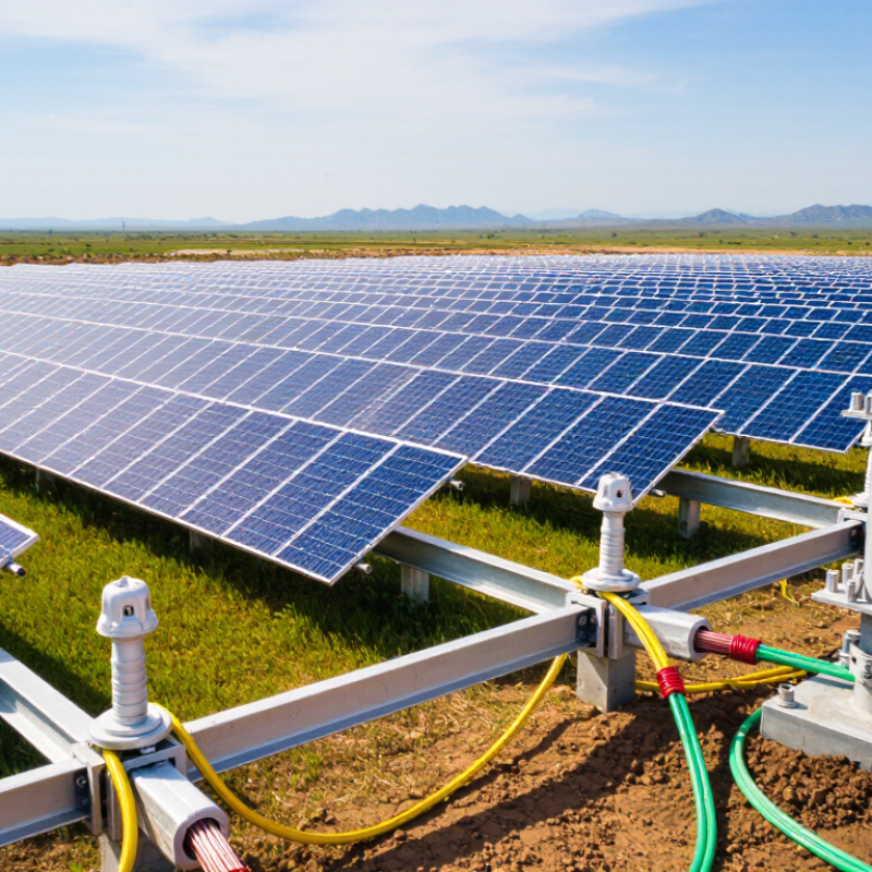
| 1 |
Protective earthing of exposed conductive parts |
Module frames, mounting structures, inverter enclosures, and other accessible metal parts, where required by equipment design and the electrical installation. |
Provides a fault-current path and helps protective devices disconnect the supply during an insulation fault. |
Use appropriately sized protective conductors and reliable, corrosion-resistant connections. Verify continuity and connection integrity during commissioning and maintenance. |
| 2 |
Equipotential bonding |
Bonding electrically conductive PV structures and relevant electrical enclosures within an array or plant. |
Reduces hazardous potential differences between accessible conductive parts. |
Identify all parts that require bonding under the project design. Check continuity across joints, coatings, hinges, and expansion connections. |
| 3 |
TN-S earthing arrangement |
PV installations supplied by, or connected to, a low-voltage system with separate neutral and protective conductors throughout the relevant circuit. |
Supports fault clearance through a dedicated protective-conductor path. |
Keep neutral and protective conductors separate. Confirm the supply arrangement, conductor sizing, protective-device coordination, and fault-loop conditions. |
| 4 |
TN-C-S earthing arrangement |
Installations where a combined protective and neutral conductor is separated into distinct conductors at a designated point in the supply system. |
Provides protective earthing while allowing the supply network to use a combined conductor upstream of the separation point. |
Make the separation only at the designated point; do not reconnect neutral and protective conductors downstream. Confirm the arrangement with the network operator and project design. |
| 5 |
TT earthing arrangement |
Sites where the installation’s exposed conductive parts are connected to a local earth electrode, independently of the supply neutral earthing arrangement. |
Provides a local protective-earth reference where a supply-provided protective conductor is not used. |
Coordinate the electrode and residual-current protection. Measure and assess earth-electrode resistance against the applicable design and protection requirements. |
| 6 |
Vertical earth-rod electrode system |
Ground-mounted PV plants or substations where suitable soil depth and site conditions allow driven or installed vertical electrodes. |
Connects the earthing network to the surrounding soil and can contribute to fault-current dissipation. |
Electrode number, length, spacing, and material depend on soil resistivity, corrosion conditions, and the design target. Inspect joints and measure the completed earth system. |
| 7 |
Horizontal buried conductor or ring electrode |
Perimeter earthing and interconnected buried conductors around PV arrays, inverter stations, or other plant areas. |
Creates an interconnected earth network and helps manage potential differences across a site. |
Design burial depth, conductor routing, cross-section, and connections for site conditions. Check for mechanical damage, corrosion, and continuity before backfilling. |
| 8 |
Foundation or concrete-encased electrode |
Buildings, equipment foundations, or other structures where an electrode can be incorporated into concrete during construction. |
Uses the structure’s foundation as part of the earthing arrangement when permitted by the design and construction details. |
Coordinate electrode materials and connection points before concrete placement. Protect accessible connections and document concealed work for future inspection. |
| 9 |
Lightning protection system bonding and coordination |
PV sites with an external lightning protection system or a lightning-risk assessment that calls for lightning-protection measures. |
Coordinates lightning-current paths and reduces dangerous potential differences and flashover risk. |
Coordinate air-termination, down-conductor, earthing, separation-distance, and bonding design. Select surge protective devices and routing in accordance with the project risk assessment and applicable standards. |
| 10 |
Transformer and inverter station earthing network |
PV plants with transformer stations, switchgear, inverter stations, or other medium-voltage equipment. |
Provides protective earthing for station equipment and addresses touch- and step-voltage concerns during faults. |
Coordinate the station grid with the plant earthing network and protection scheme. Assess fault-current magnitude and duration, soil conditions, touch and step voltages, and equipment bonding. |
 SDEV Charger